Example 02.02: Texture filtering & MIP mapping

I must say that I had a lot of fun reading up on this. I had come across most of the terms in this post before when glancing over option screens for games, but I never really deeply understood the difference betwen bilinear or anisotropic texture filtering. Let alone understand what a mipmap was. I actually really enjoy knowing what is going on under the hood :).

In the previous example we did not configure any sampler_state settings and just used the default ones. That turns out to use the fastest way of sampling the texture, using point sampling, and that leaves us with a lot of ugly artefacts.

point_sampling_no_mipmapping

Figure 1. Eeeeewwwww!
Only click for the full size version if you have a strong stomach…

So lets try and use some filtering methods to make this look better. The first thing we need to look at is actually not a texture filtering method but another method to increase rendering speed and reduce aliasing artefacts called MIP mapping.

A mipmap is a sequence of progressively lower resolution versions of the base texture. This way we can use a lower resultion version of the texture when the object is farther away from the camera. It’s a lot faster looking up the texel color from the lower resolution version then averaging the color of almost your entire image to get the pixel color when the object is far away. And you can apply any crazy filtering method to generate the lower resolution versions as you don’t have to do it in real-time. All it costs is some extra storage space, about a third of the original texture.

crate_mipmaps

Figure 2. MIP mapped crate texture

no_mipmaps_vs_mipmapped

Figure 3. Regular vs mipmapped texture

There are tools you can use to create mipmaps for your textures like the compressonator or the newer AMD compress (I actually haven’t tried that last one yet). These tools have loads of options to optimize your textures, but I’m lazy so I just ticked the option ‘Generate Mipmaps’ in the Content Processor options for my texture.

Now that we have the mipmaps for our texture, let’s apply some filtering. I will go trough the options going from fastest and crudest to the most intensive and highest quality one.

I’m giving special mention to the opengl-tutorial.org for having clear information on the subject (and all the tutorials on the site are a great intro to modern OpenGL).

Point sampling (aka Nearest-neighbor interpolation)

sampler_state
{
  MinFilter = point;
  MagFilter = point;
  MipFilter = None;
}

This basically uses no filtering and just takes the texel color that is at the UV coordinates.

nearest

Figure 4. Point Sampling

Bilinear filtering

sampler_state
{
  MinFilter = linear;
  MagFilter = linear;
  MipFilter = point;
}

Bilinear filtering is taking the four nearest texels into account and those colors are combined using the weighted average according to the distance of the UV coordinates to those texels. This smoothes out the hard edges.

linear1

Figure 5. Bilinear sampling

Bilinear filtering is mostly used in combination with mipmaps because it would suffer much of the same artefacts of point sampling if you don’t use mipmaps. The thing to note here is that the MipFilter is set to point. This means that the nearest mipmap level is chosen and then bilinear filtering is applied.

Trilinear filtering

sampler_state
{
  MinFilter = linear;
  MagFilter = linear;
  MipFilter = linear;
}

Trilinear filtering is an extension to the bilinear filtering method where not only the nearest mipmap level is sampled but the two neares mipmap levels and then linearly interpolation the results. This gives a smoother boundary at the places where we switch from one mipmap level to the next.

bilinear_vs_trilinear

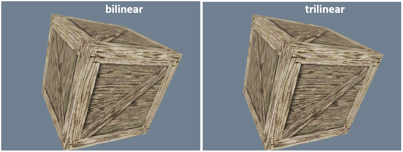
Figure 6. Bilinear vs Trilinear sampling

I must admit that I’m a bit dissapointed about my example above, you can barely make out where the mipmap level changes and the texture becomes more blurry in the bilinear case.  There are certainly more convincing cases to be found.

Anisotropic filtering

sampler_state
{
  MinFilter = anisotropic;
  MagFilter = anisotropic;
  MipFilter = linear;
  MaxAnisotropy = 16;
}

And finally we get to anisotropic filtering which is most noticable with surfaces that are at a high angle relative to the camera. In that case, the fill area for a pixel will not be square but rather trapezoidal in shape. Anisotropic filtering samples the texture as a non-square shape. Some implementations simply use rectangles instead of squares (as depicted in the picture below). Anisotropic filtering will calculate the colour in the fill area by taking a fixed number of samples configured by the MaxAnisotropy setting.

aniso

Figure 7. Anisotropic sampling

trilinear_vs_anisotropic

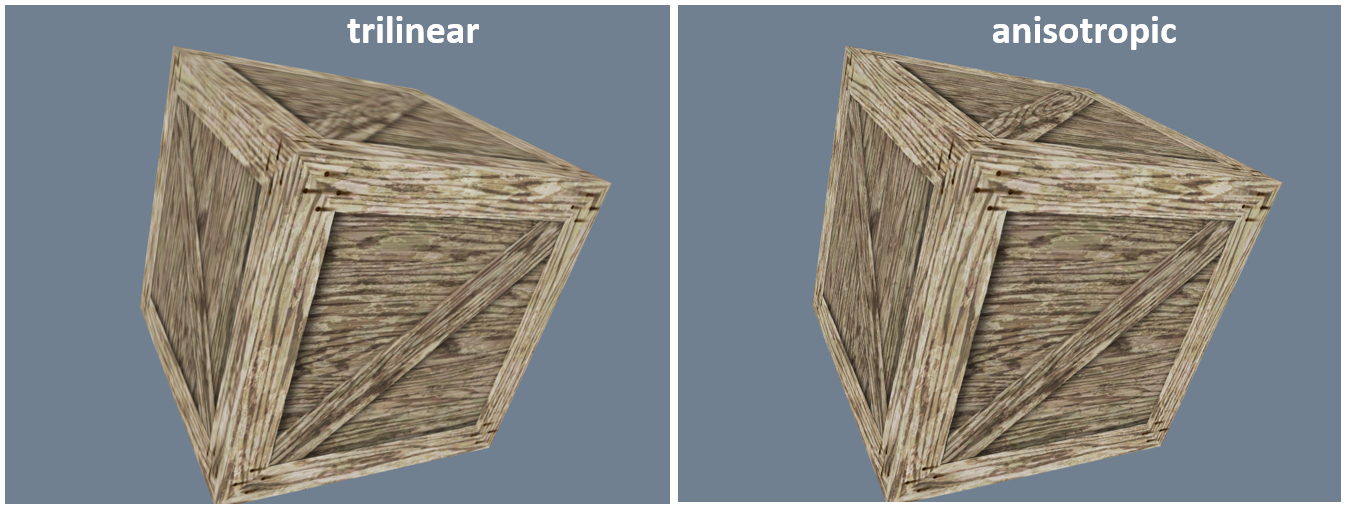
Figure 8. Trilinear sampling vs Anisotropic sampling

This is a big improvement, the texture becomes a lot less blurry on the sides of the crate. It typically does not get any better than this (yet) on consumer graphics cards.

The Code

The only code that was added building on the previous example has nothing to do with the texture filtering.

First it was necessary to add some debug text to show the active filtering mode.

 SpriteBatch _spriteBatch;  
 SpriteFont _consolasFont;
  
 protected void DrawText()  
 {  
  _spriteBatch.Begin();  
  ...  
  _spriteBatch.DrawString(_consolasFont, mipmappingText, new Vector2(10f, 50f), Color.White);  
  ...        
  _spriteBatch.End();  
 }  

Code Snippet 1. Drawing tekst with SpriteBatch

A thing worth mentioning is that SpriteBatch changes some rendering settings on the GraphicsDevice so before rendering our 3D object we must set the necessary settings back like we want them or we will have unexpected results.

 _graphicsDM.GraphicsDevice.BlendState = BlendState.Opaque;  
 _graphicsDM.GraphicsDevice.DepthStencilState = DepthStencilState.Default;  

Code Snippet 2. Reset settings on GraphicsDevice

The second thing that was added is a simple switch to select a different Technique in the shader that uses a different texture filtering method.

 switch (_currentSamplingMethod)  
 {  
  case TextureSamplingMethod.Point:  
   _effect.CurrentTechnique = _effect.Techniques["PointSampling"];  
   break;  
  case TextureSamplingMethod.Bilinear:  
   _effect.CurrentTechnique = _effect.Techniques["BilinearSampling"];  
   break;  
  case TextureSamplingMethod.Trilinear:  
   _effect.CurrentTechnique = _effect.Techniques["TrilinearSampling"];  
   break;  
  case TextureSamplingMethod.Anisotropic:  
   _effect.CurrentTechnique = _effect.Techniques["AnisotropicSampling"];  
   break;  
 }  

Code Snippet 3.  The if-then for advanced programmers: a switch statement!

Downloads

Download XNA code
Download MonoGame code

Posted in Uncategorized | Tagged | 1 Comment

Example 02.01: Diffuse Color Mapping

In the previous examples we had an object without a color of it’s own, we just used the color of the light to make it blue. So one of the first things I wanted to investigate next was how to apply a texture to a model.

I typically tought about a texture as just an image, but then I learnt that textures can be used for a lot of things. So what I tought about when talking about a texture is a 2D matrix with the diffuse color values (sounds way more impressive then ‘image’ right?).  This is why a ‘regular’ texture is often called the diffuse color map. (We’ll get into all sorts of other mappings of values using textures in the following examples).

We are typically going to use normalized texture coordinates to address a color value in the texture (= a texel). The two axis that we use are called U and V and are defined as follows:

normalized_texture_coordinates

Figure 1. Normalized texture coordinates

A big advantage of using normalized texture coordinates is that you can swap out the texture for a higher / lower resolution version and don’t have to change the addressing.

For these examples we’ll use a simple box model where the texture can be applied to. For simplicity’s sake we’ll just use the same texture on all sides. This means we’ll start with a special case and apply the same UV mapping coördinates to the four sides (or faces) of the cube.

uv_mapping

Figure 2. UV mapping for one face of the box model

The Code

The first thing we’ll do is load the texture image as a Texture2D object.

 Texture2D _texture;  
 protected override void LoadContent()  
 {  
  _texture = Content.Load("crate_diffuse");  
 }  

Code Snippet 1. loading a texture

And then it’s just a matter of initializing our shader parameter DiffuseTexture with the Texture2D object.

 protected override void Draw(GameTime gameTime)  
 {  
  ...  
  _effect.Parameters["DiffuseTexture"].SetValue(_texture);  
  ...  
 }  

Code Snippet 2. initializing the shader parameter

The new parameters that are of interest are the actual texture2D variable that holds a reference to the texture. And we also have a sampler2D parameter that defines how the texture must be sampled. For now we just bind the sampler to the DiffuseTexture with all the default states.

 texture2D DiffuseTexture;  
 sampler2D DiffuseSampler = sampler_state  
 {  
  Texture = DiffuseTexture;  
 };  

Code Snippet 3. shader parameters

In the vertex shader, we just pass down the texure coordinates we get as input from using the TEXCOORD0 semantic.

 struct VS_IN  
 {  
  float4 Pos : POSITION0; // Position (Model Space)  
  float2 Tex : TEXCOORD0; // Texture coordinates (UV)  
 };  
 VS_OUT VertexShaderFunction(VS_IN input)  
 {  
  VS_OUT output;  
  output.Pos = mul(input.Pos, WorldViewProjection);  
  output.Tex = input.Tex;  
  return output;  
 }  

Code Snippet 4. Vertex shader function

And at the pixel shader level we ask the DiffuseSampler for the value from our DiffuseTexture using the passed down texture coordinates in the built-in function tex2D().

 float4 PixelShaderFunction(VS_OUT input) : COLOR  
 {  
  return tex2D(DiffuseSampler, input.Tex);  
 }  

Code Snippet 5. Pixel shader function

I added a sort of ‘bouncing’ effect to the model.  That way you can spot the artefacts you get from the used texture filtering method (We’ll get into filtering methods in the next post).  You can press space to pause the animation and have a closer look.

Have fun!

Downloads

Download XNA code
Download MonoGame code

P.S.: Two remarks on converting the code from XNA to MonoGame. The first was that the .tga texture gave errors in the processing of the Content Pipeline tool for MonoGame.  TGA textures should be supported but I did not spend to many time investigating what was going wrong, I just worked around the problem by converting the texture to a PNG format.
The Second thing was that the box model was a lot smaller when importing it to MonoGame.  I just set the scale setting in the Content pipeline tool to 100 and that gave me the same result as in XNA.

Posted in Uncategorized | Tagged | Leave a comment

Example 01.04: Phong reflection model – specular lighting

It’s finally time to implement the specular lighting part of the shader and hopefully get something resembling the wikipedia article.

01_01_figure_1

Figure 1. The different components of the Phong equation

Specular reflection is the mirror-like reflection you get on shiny surfaces, it shows as a spot of bright light on an object.

specular_ligthing

In the Phong reflection model this is calculated as:

specular_vectors

|R|.|V|.cos(β)n

Where V is the view vector, it poits to the eye (or camera). R is the reflection vector for the incoming light (or incident ray) calculated by the formula below and β is the angle between R and V.  The exponent n is what is called the Phong exponent.  It’s an arbitrarily chosen value that determines the shinyness of a surface.

reflection_vector2

2(N·L)N-L

The Geometric representation above shows how we get the reflection vector R by taking the dot product of the normal vector N and light vector L, doubling that and multiplying it by the normal vector N.  And finally adding that to the negative light vector L so we end up with R, the reflection vector.

Having understood all that, let’s never do that again and just use the built-in HLSL function reflect() that gives you the reflection vector.  But one of my favourite books mentions on page 400 that it’s a favourite question on job interviews when seeking a job in the video game industry.  Not that that’s an ambition that I have, and if you have it you probably should find more reliable sources to learn from than this blog…

Adding these vectors to those we have from the previous examples, all the vectors we need for our calculations are shown in the image below.

phong_vectors

Figure 2. All vectors needed for the Phong calculations

The Code

As is becoming usual, more parameters need to be initialized. We have the specular color (Sc), specular intensity (Si), specular power (Sp) (this is the phong exponent that controls the shinyness) and the eye or camera position (vEyePosition), however you like to call it.

 _effect.Parameters["Si"].SetValue(0.8f);  
 _effect.Parameters["Sc"].SetValue(new Vector4(1.0f, 1.0f, 1.0f, 1.0f));  
 _effect.Parameters["Sp"].SetValue(30f);  
 _effect.Parameters["vEyePosition"].SetValue(_cameraPosition);  

Code Snippet 1. Initialization of specular reflection parameters

As we are doing all our lighting calculations in world space, the vertex shader function adds the world position to it’s output for use in the pixel shader.

 VS_OUT VertexShaderFunction(VS_IN input)  
 {  
  VS_OUT output;  
  output.Pos = mul(input.Pos, matWorldViewProj);  
  output.WorldPos = mul(input.Pos, matWorld);  
  output.N = mul(input.N, matWorld);  
  return output;  
 }  

Code Snippet 2. Vertex shader function

All the fun is happening in the pixel shader function to get the most aesthetically pleasing image. As a performance optimization you can move some (or even all) lighting calculations to the vertex shader level because the code will be called a lot less as there will be a lot less vertices than pixels. But on models with low polygon count the lighting does not look very nice.

We’re not going to calculate the reflection vector manually but rather use the handy built-in function reflect() to get it.

 float4 PixelShaderFunction(VS_OUT input) : COLOR  
 {  
  float3 N = normalize(input.N);  
  float3 L = normalize(vLightDirection);  
  float3 V = normalize(vEyePosition - input.WorldPos);  
  float diffuseFactor = saturate(dot(L, N));  
  float3 R = reflect(-L, N);  
  float specularFactor = pow(saturate(dot(R, V)), Sp);  
  return Ai * Ac + Di * Dc * diffuseFactor + Si * Sc * specularFactor;  
 }  

Code Snippet 3. Pixel shader function

And that’s looking pretty close to the image I was trying to bring to life.

I’ll put in an obscure reference to those familiar with The Little Lisper/Schemer (if you are not, you’re missing out!  Go read that book!): I think I’ve earned my peanut butter and jelly sandwich now… 🙂

Have fun!

previous post

Downloads

Download XNA code
Download MonoGame code
Blob model

Posted in Uncategorized | Tagged | Leave a comment

Example 01.03: Phong reflection model – diffuse lighting

After the basic ambient lighting factor from the previous example, we are now actually going to apply some shading to our model. The diffuse lighting component we will implement assumes we are describing a perfect matte surface that scatters the incoming light equally in all directions.

diffuse_reflection

Figure 1. Diffuse reflection

The Code

The first thing that has changed in the code is the initialization of the extra parameters needed for the diffuse lighting equation. These are the diffuse color (Dc) the diffuse color intensity (Di) and a normalized vector for the direction the light is coming from (vLightDirection).

 _effect.Parameters["Di"].SetValue(1.0f);  
 _effect.Parameters["Dc"].SetValue(new Vector4(0.0f, 0.0f, 0.3f, 1.0f));  
 Vector3 lightDirection = new Vector3(0.0f, 1.0f, 1.0f);  
 lightDirection.Normalize();  
 _effect.Parameters["vLightDirection"].SetValue(lightDirection);  

Code Snippet 1. Setting the required parameters

As we are doing the diffuse lighting calculation in world space we need to have the world matrix separately available in the shader. Typically the surface normals of a model are given for each vertex in model space. The light vector we use here is defined in world space so to convert the normal vectors from model to world space we need the world matrix.

 _effect.Parameters["matWorld"].SetValue(modelPartWorldMatrix);  

Code Snippet 2. Setting the world matrix

In the shader we start by adding the vertex normal to the input structure for our vertex shader function. By adding the semantic ‘: NORMAL’ we kindly ask the API that if normal data is available for the vertex, please fill it in here.

struct VS_IN  
{  
  float4 Pos : POSITION; // Position (Model Space)  
  float3 N : NORMAL; // Normal (Model Space)  
};  

Code Snippet 3. Vertex shader input

In the vertex shader function we simply convert the normal vector from model to world space and pass it along to the pixel shader.

VS_OUT VertexShaderFunction(VS_IN input)  
{  
  VS_OUT output;  
  output.Pos = mul(input.Pos, matWorldViewProj);  
  output.N = normalize(mul(input.N, matWorld));  
  return output;  
}  

Code Snippet 4. Vertex shader function

As with most things you pass down in the graphics pipeline, the vertex normal you receive in the pixel shader input will be interpolated. As the interpolation process can make the normal vector denomalized, we need to normalize it again to correctly calculate the diffuse lighting factor (or Lambert factor).

triangle_normals

Figure 2. A triangle with normal vectors defined for each vertex

normal_interpolation

Figure 3. Denormalization of normal vector due to interpolation

The Lambert factor is the scalar that the diffuse light must be multiplied with to get the correct light intensity. It’s the cosine of the angle between the light direction and the surface normal. As both the surface normal and light vector are normalized, the cosine of the angle between them is actually the same as the dot product of the vectors. A formula for getting the dot product of vectors N and L is: |N| . |L| . cos(α)

diffuse_vectors

As our nomal and light vectors are normalized, their magnitudes are 1 and the dot product just gives us the cosine of the angle between them that we were after.

One of the best explanations on vector dot products I’ve ever read is in chapter 2.11 of ‘3D Math Primer for Graphics and Game Development‘. The geometric interpretation, seeing it as a ‘projection’, is very usefull.

Shading languages have performant implementations of vector operations so using the built-in HLSL functions this translates to: saturate(dot(L, N)).  Where L is the vector that points to the light source and N is the normal vector of the surface.  The saturate function clamps the value between 0 and 1 as we don’t want negative lighting values.

float4 PixelShaderFunction(VS_OUT input) : COLOR  
{  
  float3 N = normalize(input.N);  
  float3 L = normalize(vLightDirection);  
  return Ai * Ac + Di * Dc * saturate(dot(L, N));  
}  

Code Snippet 5. Pixel shader function

So now our model is actually beginning to look like something with a little depth to it.

Have fun!

previous post – next post

Downloads

Download XNA code
Download MonoGame code
Blob model

Posted in Uncategorized | Leave a comment

Example 01.02: Phong reflection model – ambient lighting

We’ll start of with what I call an arbitrary ‘smudge’ factor: Ambient lighting.  This represents the light in the scene that is scattered of nearby objects and uniformly lits our object.  We just assume that the light has bounced around so many times that it appears to be coming from everywhere, uniformly distributed.

ambient_lighting

Figure 1. Ambient Lighting

A way to do this right seems to be implementing some form of global illumination , but I’m getting way ahead of myself here as usual.  I have a tendency to start looking something up and end up hours later reading about all kinds of advanced graphics wizardry.  Let’s just get back to the basic Phong reflection model and stick with the simple ambient lighting factor for now :).

In this case we’ll choose a soft blue color to match the wikipedia example image that we’re trying to bring to life.

Before starting with the code I just want to thank digitalerr0r for the great XNA Shader Tutorials on his blog that I used as a basis for these examples.

The Code

The only thing that’s added in our project code is the initialization of the two parameters for ambient lighting: color (Ac) and intensity (Ai).

_effect.Parameters["Ai"].SetValue(0.8f);  
_effect.Parameters["Ac"].SetValue(new Vector4(0.0f, 0.0f, 0.3f, 1.0f));  

Code Snippet 1. Setting the parameters

The vertex shader function stays the same as in the previous example but we change the pixel shader to the following

float4 PixelShaderFunction(VS_OUT input) : COLOR  
{  
  return Ai * Ac;  
}  

Code Snippet 2. Pixel shader function

And in the shader pass we also remove the render state settings from last time so it’s just:

technique DefaultTechnique  
{  
  pass P0  
  {  
   VertexShader = compile vs_2_0 Wireframe_VS();  
   PixelShader = compile ps_2_0 PixelShaderFunction();  
  }  
}  

Code Snippet 3.  Shader pass

Now we have a boring, uniformly colored blob.  Yay!  It doesn’t have much depth to it yet because shading and specular hightlights still need to be added.

Have fun!

previous post – next post

Downloads

Download XNA code
Download MonoGame code
Blob model

Posted in Uncategorized | Tagged | Leave a comment

Example 01.01: Implementing a shading algorithm

When looking around for examples on writing a shader program in HLSL I stumbled upon various ways of writing a basic shader.

At the core of all this, for rendering opaque surfaces, is the Bidirectional Reflectance Distribution Function (BRDF)  that you choose to implement. It’s a function that determines the distribution of reflected light based on two directions: the view (or camera) direction and the light direction.

brdf

Figure 1. Distribution of reflected light

So why not start at the beginning with one of the earliest models: the Phong reflection model. This was first published in 1973, seven years before I was even born, thats prehistoric in the field of computer science!  After seeing the picture below on wikipedia I thought to myself: “Hey, I can do that, how hard could it be?”. We all know the hard work that comes after that thought, right? 🙂

01_01_figure_1

Figure 2. The different components of the Phong equation

Now the first thing that I need is that nice blob model that will show off some interesting shading and reflection. As I’m doing this series to learn, why not jump in the deep end and try to create that model myself. There are a few well known commercial 3d modeling applications (3D Studio Max, Maya, ZBrush,…) but as I am doing this for fun, a free / open source modeling program sounded like music to my ears. The best know, fully featured, open-source 3d modeling tool is probably Blender.  So that’s the tool that I picked for the job.

I had read that the user interface of Blender was an acquired taste and I can confirm that most things did not work as I initially thought they would. So after a long and rather frustrating evening figuring out the basics of Blender I ended up with this:

blender_blob

Figure 3. A blob is born

It may not look like much, but I was pretty proud of the result. Now let’s render this thing!

The Code

Most initialization code is the same as in the spaceship sample, the one new thing is that we’ll use the proper bone transforms. I hope I get this right, but as far as I understand it, the position of each mesh part of a model is dependent of their parent bone position. So if you move the bone, all meshparts move with it.

_model = Content.Load("phong_object");  
_bones = new Matrix[_model.Bones.Count];  
_model.CopyAbsoluteBoneTransformsTo(_bones);  

Code Snippet 1. Bones transforms

The draw portion for each frame is again pretty similar to the spaceship sample, but we are using a custom shader here instead of the BasicEffect and taking the bone transforms into account. We loop all the passes of the shader, but our shader only has one pass for now. When using a custom shader we can’t use the built-in draw function of the ModelMesh class so we just set the vertex and index buffer and then call DrawIndexedPrimitives for each mesh part.

 GraphicsDevice.Clear(Color.Black);  
 foreach (ModelMesh mesh in _model.Meshes)  
 {  
  foreach (ModelMeshPart part in mesh.MeshParts)  
  {  
   // calculate WorldMatrix  
   var modelPartWorldMatrix = _bones[mesh.ParentBone.Index] * _worldMatrix;  
   _effect.Parameters["matWorldViewProj"].SetValue(modelPartWorldMatrix * _viewMatrix * _projectionMatrix);  
   foreach (EffectPass pass in _effect.CurrentTechnique.Passes)  
   {  
    pass.Apply();  
    // Render meshpart  
    _graphicsDM.GraphicsDevice.SetVertexBuffer(part.VertexBuffer);  
    _graphicsDM.GraphicsDevice.Indices = part.IndexBuffer;  
    _graphicsDM.GraphicsDevice.DrawIndexedPrimitives(PrimitiveType.TriangleList, part.VertexOffset, 0, part.NumVertices, part.StartIndex, part.PrimitiveCount);  
   }  
  }  
 }  

 Code Snippet 2. drawing the model

I just wanted to get the wireframe rendered as a first step before beginning to implement the first component of the Phong reflection model. The resulting shader is the most minimalistic yet.

In the vertex shader function we define a combined world-view-projection matrix and transform all vertices with that.

 float4x4 matWorldViewProj;  
 VS_OUT VertexShaderFunction(VS_IN input)  
 {  
  VS_OUT output;  
  output.Pos = mul(input.Pos, matWorldViewProj);  
  return output;  
 }  

Code Snippet 3. Vertex shader function

And our pixel shader function simply returns the color white.

float4 PixelShaderFunction(VS_OUT input) : COLOR
{
  return float4(1.0, 1.0, 1.0, 1.0);
}

Code Snippet 4. Pixel shader function

The only trick we need to apply to get only the wireframe rendered and not rasterize the surface in between is set the FillMode to WireFrame. We also set the CullMode to None so the triangles facing away from the camera are not culled.

 technique DefaultTechnique  
 {  
  pass P0  
  {  
   CullMode = None;  
   FillMode = WireFrame;  
   VertexShader = compile vs_2_0 VertexShaderFunction();  
   PixelShader = compile ps_2_0 PixelShaderFunction();  
  }  
 }  

Code Snippet 5. Shader pass

That’s all for now, in the next example we’ll start implementing the Phong reflection model.

Have fun!

next post

Downloads

Download XNA code
Download MonoGame code
Blob model

Posted in Uncategorized | Tagged | Leave a comment

Example 00.02: Using a custom shader

Allright, in the first example I have skipped over the cannonical example of rendering a single triangle for something more complex like rendering a fully shaded and textured spaceship.  And now I’m sorry and I want to scale back down to the triangle before writing my first custom shader in HLSL.  The shader that I would have to write to replicate the previous example is way to complex for a first shader.

The Code

Instead of loading the model data from a file like last time, we’ll just define three vertices in code, each with a different color. To render them we just set the VertexBuffer to the vertices and render them as a TriangleList.

 VertexPositionColor[] vertices = new VertexPositionColor[3];  
 vertices[0] = new VertexPositionColor(new Vector3( 0f, 1f, 0f), Color.Red);  
 vertices[1] = new VertexPositionColor(new Vector3( 1f, -1f, 0f), Color.Green);  
 vertices[2] = new VertexPositionColor(new Vector3(-1f, -1f, 0f), Color.Blue);  
 _vertexBuffer = new VertexBuffer(GraphicsDevice, typeof(VertexPositionColor), 3, BufferUsage.WriteOnly);  
 _vertexBuffer.SetData<VertexPositionColor>(vertices);  

Code Snippet 1. Define vertices and write them to the vertex buffer

Instead of using the BasicEffect we’ll use a custom shader (or effect as it’s called in XNA).

 _effect = Content.Load<Effect>("custom");  
 GraphicsDevice.Clear(Color.Black);  
 _effect.Parameters["World"].SetValue(_worldMatrix);  
 _effect.Parameters["View"].SetValue(_viewMatrix);  
 _effect.Parameters["Projection"].SetValue(_projectionMatrix);  
 GraphicsDevice.SetVertexBuffer(_vertexBuffer);  
 foreach (EffectPass pass in _effect.CurrentTechnique.Passes)  
 {  
   pass.Apply();  
   GraphicsDevice.DrawPrimitives(PrimitiveType.TriangleList, 0, 1);  
 }  

Code Snippet 2. Rendering the vertices in the vertex buffer with a custom shader

The most interesting thing about this example is the shader code in HLSL. This is the first time I’ve written something in HLSL and while the language itself is fairly simple, there are a lot of concepts to learn about how the code you write fits in the programmable graphics pipeline of a contemporary graphics card. One of my personal favorite series on the subject with lots of detail is: The Cg Tutorial on the nvidia site. The tutorial is about Cg an not HLSL but it’s a great introduction to the key concepts of shader programming.

This first shader is about as simple as they get. We just transform all vertices from model space to screen space (aka clip space) by multiplying them with the combined world, view and projection maxtrix. The vertex position in clip space is actually a mandatory output for a vertex shader function because it’s needed by the steps further down the pipeline. The reason for using matrices for the transformation is really because we can combine these transformations and then just transform each vertex by multiplying it to the combined matrix. I did it in three separate operations here and I will generally not make the typical performance optimizations in these examples as my main focus is learning something.

We also forward the color for the vertex to the pixel shader. This color will be interpolated with the other vertex colors by a following stage in the pipeline.

 VertexShaderOutput VertexShaderFunction(VertexShaderInput input)  
 {  
   VertexShaderOutput output;  
   float4 worldPosition = mul(input.Position, World);  
   float4 viewPosition = mul(worldPosition, View);  
   output.Position = mul(viewPosition, Projection);  
      output.Color = input.Color;  
   return output;  
 }  

Code Snippet 3. The vertex shader function

And in the pixel shader function we just return the interpolated color as the color for the pixel (aka fragment).

 float4 PixelShaderFunction(VertexShaderOutput input) : COLOR0  
 {  
   return input.Color;  
 }  

Code Snippet 4. The pixel shader function

And that’s all there’s to it.  I have what I was after, a basic project with a custom shader to start from for the other examples.

Have fun!

previous post

Downloads

Download XNA code
Download MonoGame code

P.S. When converting this example from XNA to MonoGame I had to upgrade to Shader Model 4.  This led me to the discovery that the semantic for the position of the vertex shader input needed to be changed to SV_POSITION instead of POSITION.

Posted in Uncategorized | Tagged | Leave a comment

Example 00.01: Hello World

As a first example I just wanted to make a classic ‘Hello world’ example. This gives me a basic ’empty’ project to do the other examples in.

One of the things I really wanted to do is writing custom shaders and learning some HLSL. In this example I’ll just stick with the built-in default shader (BasicEffect) but in the following example I’ll swap this out with a custom one.

The canonical first example in graphics programming seems to be rendering a single triangle with the three vertices of your triangle in a different color so you can see the color interpolation by the graphics pipeline.

00_01_figure_1

Figure 1. A single triangle in all it’s glory

As I’ll be using XNA / MonoGame it’s actually even less code to just load up and entire model with default lighting settings and render that to screen. Not to mention that it looks a lot cooler ;).

The Code

Our model (in this case p1_wedge.fbx) has it’s vertices defined in model space (3d) and we need to transform those to screen space (aka clip space) coordinates (2d) when rendering a frame. To make a long and interesting story short it turns out that using matrices to convert between the coordinate spaces is the most efficient way to do this.

The first matrix is the world matrix that puts our model somewhere in our virtual world.  For now we will only scale the model down and not move or rotate it.

 _worldMatrix = Matrix.CreateScale(_modelScale);  

Code Snippet 1. World Matrix

Then we initialize our view matrix that will turn everything in our world around so the camera position is at the origin of the coordinate space and points down the Z-axis. This reminds me that I did not mention there is a difference between left- and right handed coordinate spaces.  XNA / MonoGame uses a right handed coordinate system.

 Vector3 cameraPosition = new Vector3(-15f, 15f, -25f);  
 _viewMatrix = Matrix.CreateLookAt(cameraPosition, Vector3.Zero, Vector3.Up);  

Code Snippet 2. View Matrix

And finally we have our projection matrix. This matrix describes how we project our 3d vertices onto our 2d screen.

 float fieldOfView = (float)Math.PI / 2f;  
 float aspectRatio = (float)_graphicsDM.GraphicsDevice.Viewport.Width / (float)_graphicsDM.GraphicsDevice.Viewport.Height;  
 float nearPlane = 10f;  
 float farPlane = 50f;  
 _projectionMatrix = Matrix.CreatePerspectiveFieldOfView(fieldOfView, aspectRatio, nearPlane, farPlane);  

Code Snippet 3. Projection Matrix

Now that we have the minimum of necessary initialization done, we can render our model. This code goes through a few simple steps:

  •  It starts with clearing the screen to SlateGray
  •  Then we loop every Mesh in the Model
  •  Then we loop every BasicEffect of the Mesh
  •  We set the world, view and projection matrices for the BasicEffect and enable the default lighting model
  • And finally we draw each mesh
 GraphicsDevice.Clear(Color.SlateGray);  
 foreach (ModelMesh mesh in _model.Meshes)  
 {  
   foreach (Microsoft.Xna.Framework.Graphics.BasicEffect effect in mesh.Effects)  
   {  
     effect.World = _worldMatrix;  
     effect.View = _viewMatrix;  
     effect.Projection = _projectionMatrix;  
     effect.EnableDefaultLighting();  
   }  
   mesh.Draw();  
 }  

Code Snippet 4. Drawing a Model

In my opinion, this is where XNA / MonoGame really shines. A lot of the plumbing is done for you and you can get something reasonable on the screen with very few lines of code.

00_01_figure_2

Figure 2. Spaceship rendered with default ligthing settings in XNA

We are stuck with a pretty boring 2d image at the moment, not what I had in mind when rendering something in 3d in real-time. So let’s just add another matrix (because everybody loves a matrix, right?) that holds the amount of rotation to rotate our model 360 degrees in 5 seconds. And then we just multiply the original world matrix (the scaling) with the roation matrix every time before rendering the next frame.

 _modelRotation -= (float)gameTime.ElapsedGameTime.Milliseconds * (MathHelper.TwoPi / 5000f);  
 _worldMatrix = Matrix.CreateScale(_modelScale) * Matrix.CreateRotationY(_modelRotation);  

Code Snippet 5. Rotate the model


Aaah, now I’m happy, at least now you can see the shading change when as it spins around. I hope you are happy too, this will be all for now.

Have fun!

next post

Downloads

Download XNA code
Download MonoGame code
Spaceship model

P.S.: A little sidenote on the MonoGame version. The MonoGame content pipeline tool was not very happy with the original p1_wedge.fbx model so I had to convert it to a newer format (I used the Autodesk FBX converter tool) and change the reference to the texture to a relative path.

Posted in Uncategorized | Tagged | Leave a comment